| Primary Function |
Removal of moisture, acid-forming contaminants, metal particles, brazing residues, and other debris from a refrigeration or air-conditioning circuit. |
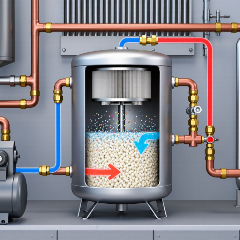
A filter-drier combines a particulate filter with a desiccant bed. The desiccant adsorbs moisture; the filter retains solid contamination. |
Select a model designed for the refrigerant, oil type, system application, and expected contamination load. |
Confirm compatibility with the refrigerant, lubricant, maximum working pressure, temperature range, and installation direction. |
| Installation Location |
The position of the component in the refrigerant circuit. |
Liquid-line filter-driers are commonly installed in the liquid line upstream of the expansion device. Suction-line filter-driers are generally used temporarily after compressor burnout or major system contamination. |
A liquid-line model and a suction-line model are not automatically interchangeable because flow conditions, pressure drop, and contamination requirements differ. |
Follow the system design and the component's approved flow direction. Check whether the device is intended for liquid, suction, or bidirectional service. |
| Refrigerant Compatibility |
Whether the construction materials and desiccant are suitable for the refrigerant and lubricant. |
Common refrigerant families include HFC, HFO, HC, ammonia, and carbon-dioxide systems, but compatibility is application-specific. |
Use only a filter-drier rated for the refrigerant, oil, pressure level, and temperature conditions in the system. |
Check the technical data sheet for approved refrigerants, oil compatibility, pressure rating, and restrictions for flammable or high-pressure refrigerants. |
| Flow Capacity |
The refrigerant mass flow that can pass through the device while maintaining an acceptable pressure drop. |
Capacity depends on refrigerant type, entering temperature, liquid quality, subcooling, pressure level, connection size, and allowable pressure drop. It cannot be selected reliably from connection size alone. |
Choose a size whose rated capacity meets or exceeds the maximum design load under the actual operating conditions. |
Compare the system's maximum mass flow with the manufacturer's capacity tables at the actual refrigerant and operating condition. |
| Pressure Drop |
The pressure loss caused by the filter element, desiccant bed, and internal flow passages. |
Pressure drop should be kept low enough to avoid flash gas in the liquid line and excessive reduction of evaporator inlet pressure. A rising pressure drop often indicates filter loading. |
Oversizing can reduce pressure drop but may increase cost and physical size; undersizing can restrict flow and reduce system capacity. |
Measure pressure or temperature before and after the device under stable load. Compare the result with the approved pressure-drop curve for the exact model. |
| Liquid-Line Pressure-Drop Screening |
A preliminary limit used to evaluate whether liquid-line restriction may affect expansion-device operation. |
Many designs aim for a small pressure loss, often around 0.1 to 0.3 bar, but the acceptable value depends on available subcooling, refrigerant, system pressure, and design conditions. |
Do not use a universal pressure-drop limit for every system. A pressure drop that is acceptable in one installation may cause flashing in another. |
Check the available liquid subcooling and calculate whether the pressure loss can cause the liquid to approach its saturation pressure before the expansion device. |
| Moisture-Removal Capacity |
The amount of water the desiccant can retain at specified temperature, refrigerant, and moisture conditions. |
Moisture capacity varies with desiccant type, quantity, refrigerant, oil, temperature, and the initial water content of the system. Published capacity is condition-dependent. |
Select sufficient capacity for the system volume and expected moisture load, especially after installation, component replacement, or exposure to atmospheric air. |
Use the supplier's moisture-capacity data and evacuate the system properly before commissioning. A filter-drier does not replace dehydration by evacuation. |
| Desiccant Type |
The chemical material used to adsorb water and, in some designs, help control acids or polar contaminants. |
Common desiccants include molecular sieve and activated alumina. Blended formulations are used when both moisture control and acid or contaminant control are required. |
Choose the formulation according to refrigerant stability, lubricant chemistry, system cleanliness, and whether acid cleanup is required. |
Review the technical documentation for moisture capacity, acid-removal capability, compatibility, and recommended application limits. |
| Moisture Indicator |
A visual indication of the approximate moisture condition of the liquid refrigerant at the indicator location. |
Many indicators use a reversible color change, but the dry and wet colors are product-specific and can also be influenced by refrigerant, temperature, and viewing conditions. |
Use the indicator as a trend and warning device, not as a laboratory measurement of total system moisture. |
Read the indicator under stable liquid-line conditions and follow the color chart supplied for that specific indicator. Investigate a persistent wet indication. |
| Moisture Indicator Location |
Where the moisture condition is observed relative to the filter-drier. |
An indicator installed downstream of the filter-drier can help show the condition of refrigerant entering the expansion device. |
The reading may not represent the moisture level throughout the entire circuit, particularly during startup, charging, or changing load conditions. |
Allow the system to stabilize and interpret the indication together with evacuation results, operating pressures, and service history. |
| Filtration Rating |
The size and quantity of solid particles retained by the filter element. |
Fine filtration improves cleanliness but can increase initial pressure drop and may load faster in a heavily contaminated system. |
Use standard liquid-line filtration for clean systems and a suitable high-capacity or suction-line cleanup device after severe contamination. |
Check the specified filtration rating, dirt-holding capacity, and recommended replacement criteria. |
| Acid-Removal Requirement |
The need to remove organic acids and other products formed by compressor motor burnout or lubricant decomposition. |
Acid cleanup generally requires a filter-drier specifically intended for burnout or severe contamination service. A standard liquid-line drier may not provide sufficient cleanup capacity. |
Use a cleanup configuration only when the failure analysis supports it, because high contamination loads can rapidly increase pressure drop. |
Test the oil or system for acid and contamination, install the appropriate cleanup device, and replace it when pressure drop or cleanup results require. |
| Connection Size and Type |
The physical interface between the filter-drier and the refrigeration piping. |
Common connections include sweat, flare, and threaded forms. Connection size must be considered together with internal flow capacity. |
A larger pipe connection does not guarantee adequate filtration or moisture capacity, while a reduced connection can create an unnecessary restriction. |
Match the connection type, nominal size, installation method, service accessibility, and flow direction to the piping design. |
| Maximum Working Pressure |
The highest pressure at which the component may operate safely within its specified temperature range. |
Pressure requirements differ substantially between conventional air-conditioning circuits, carbon-dioxide systems, and other high-pressure applications. |
The component must have a pressure rating equal to or greater than the system's applicable design and relief-device requirements. |
Compare the marked rating with the system design pressure and applicable codes before installation. |
| Temperature Range |
The allowable operating and storage temperature range of the shell, seals, desiccant, and indicator. |
Very low temperatures can affect indicator response, lubricant behavior, and pressure-drop calculations. High temperatures can affect seals and desiccant performance. |
Select a component rated for the coldest and hottest locations in the circuit, including pull-down and defrost conditions where applicable. |
Verify the component temperature rating against suction-line, liquid-line, ambient, and transient conditions. |
| Replacement Timing |
When the filter-drier should be changed after installation or contamination cleanup. |
Replacement is commonly considered after a major system repair, after compressor burnout cleanup, when the moisture indicator remains wet, or when abnormal pressure drop develops. |
Choose a serviceable arrangement that permits safe replacement without unnecessary refrigerant loss or prolonged system downtime. |
Use pressure-drop readings, moisture indication, acid-test results, and the service procedure to determine replacement timing. |
| Installation Orientation |
The physical orientation and flow direction of the device. |
Many filter-driers are directional. Incorrect orientation can reduce filtration performance or cause improper flow through the desiccant bed. |
Install the arrow in the designed flow direction and provide sufficient support to prevent vibration or tubing stress. |
Confirm the arrow marking, mounting instructions, brazing procedure, and clearance for future service. |
| Final Selection Rule |
The combined assessment of capacity, pressure drop, moisture control, compatibility, and service requirements. |
The best selection is not necessarily the largest unit; it is the unit that meets the required flow, pressure, moisture, contamination, and installation conditions with an appropriate safety margin. |
Evaluate the complete operating envelope rather than selecting by nominal tonnage or pipe diameter alone. |
Document refrigerant, maximum mass flow, operating pressures, temperatures, allowable pressure drop, moisture risk, contamination history, and service access. |



 Email
Email Whatsapp
 WeChat